Flow measurement of a wave upwelling pump
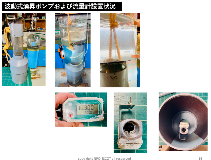
The waterproofing function of the flow meter was improved, and fittings were attached for mounting it inside the upwelling tube to measure the flow rate.
Experimental overview:
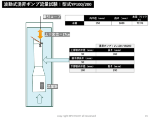
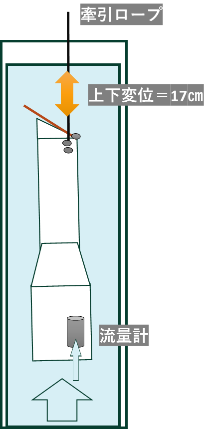
An experimental upwelling pump with a total length of 650 mm was placed in a water layer with a diameter of approximately 300 mm and a height of approximately 1,040 mm, and a “pull-up/drop” test was performed 100 times x 3 sets with a vertical displacement of 170 mm.
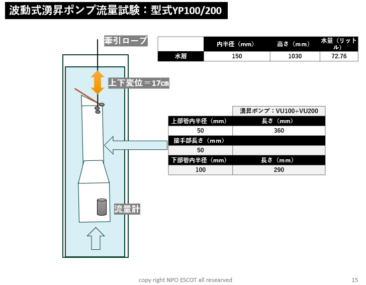
Water layer size:
| Inner radius ( mm) | Height (mm) | Water volume (liters) | |
| water layer | 150 | 1030 | 72.76 |
Experimental upwelling pump:
| Upwelling pump: VU100+VU200 | |
| Upper tube inner radius ( mm ) | Length ( mm) |
| 50 | 360 |
| Joint length (mm) | |
| 50 | |
| Lower pipe inner radius ( mm ) | Length (mm) |
| 100 | 290 |
*The same as the actual instrument except for the length of the upper and lower tubes.
Summary illustration:
Device and flowmeter images:
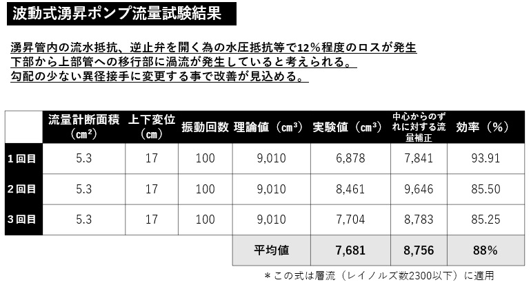
Measurement results:
| Flowmeter cross-sectional area ( cm² ) | Vertical displacement (cm) | Vibration frequency | Theoretical value ( cm³ ) | Experimental value ( cm³ ) | Off-center flow compensation | efficiency(%) | |
| First Time | 5.3 | 17 | 100 | 9,010 | 6,878 | 7,841 | 93.91 |
| Second Time | 5.3 | 17 | 100 | 9,010 | 8,461 | 9,646 | 85.50 |
| Third Time | 5.3 | 17 | 100 | 9,010 | 7,704 | 8,783 | 85.25 |
| Average | 7,681 | 8,756 | 88 % | ||||
| *This formula applies to laminar flow (Reynolds number 2300 or less). | |||||||
The amount of upwelling was about 12% lower than the theoretical value.
The reasons for this are presumed to be as follows.
Causes of decrease in pumping volume:
1. Theoretical values were calculated based on the lower upwelling pipe, but the cross-sectional area of the upper upwelling pipe is 1/4 that of the lower upwelling pipe, resulting in eddy current resistance.
2. Water pressure resistance to open the check valve
3. Friction resistance of the flowing water with the inner wall of the upwelling pipe
Measures to improve and maintain yield :
1. Lighter check valve and adjusted slant angle
2. Eliminate the growth of living organisms inside the upwelling pipe.
3. Reduce the overall weight and shorten the cycle.
4. Utilize the lifting effect when the buoy tilts.
5. Change to a different diameter joint with a smaller angle gradient.
Test result table:
The flow meter was installed 44 mm toward the wall from the center of the lower pipe with a radius of 100 mm.
Therefore, flow rate correction was performed according to the Hagen-Poiseuille law.
Climate change countermeasure mechanism of the wave upwelling device ⇒Click here
Wave upwelling pump explanation video ⇒here
NPO Escot
4-17 Azumakami-cho, Kashiwa City, Chiba Prefecture, 277-0011
Testing Center 768-22 Kamifuse, Onjuku Town, Isumi District, Chiba Prefecture
tel: +81-4-7166-4151
mobile: +81-80-4365-0861
fax: +81-4-7166-4128
https://www.npo-escot.org
ser.kashiwa@gmail.com